
Back in March, we published a blog post detailing our process of using 3D models in pre-surgical planning for a right lobe living donor hepatectomy. To continue the series, we will be moving on to our next case example - a left lateral segment living donor hepatectomy for use in pediatric liver transplant.
The 3D reconstruction software utilized by our transplant team is Intrasense Myrian, which we will be featuring in the workflow below. Myrian is used for segmentation of different vasculature and organs, as well as calculating the volumes of liver parenchyma in both the graft and remnant liver
Similar open-source plug-ins are available for 3D Slicer as well.
Simulating the cut
For a left lateral hepatectomy, the parenchymal transection line is less defined compared to a right hepatectomy, which is carried out along the plane of the middle hepatic vein. Two general guidelines are followed:
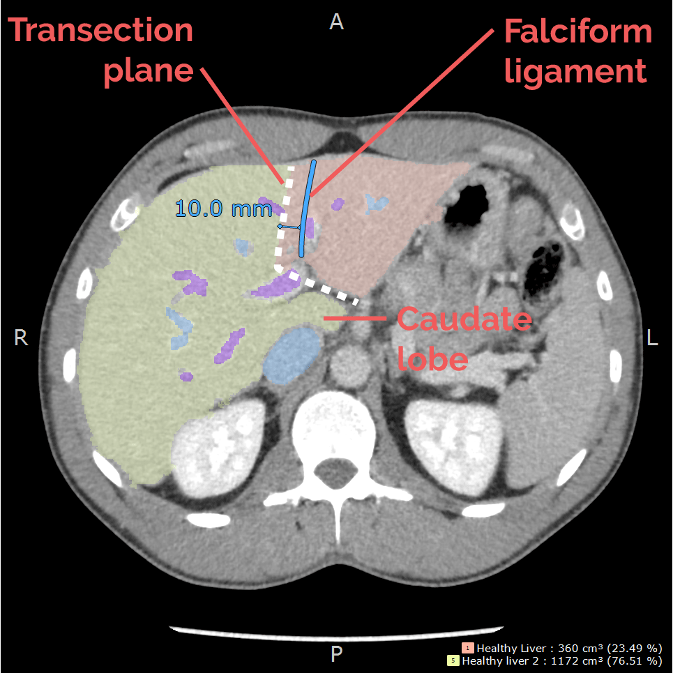
1. The transection line is through Segment 4, and is approximately 1 cm to the right of the falciform ligament towards the middle/left hepatic vein confluence.
2. The caudate lobe (segment 1) is excluded from transection and thus preserved in the donor.
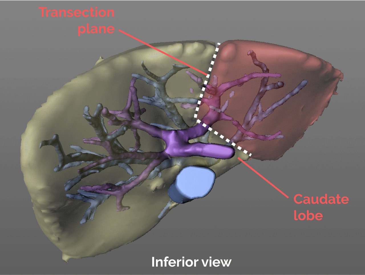
This results in a somewhat L-shaped transection plane.
Vascular structures along the plane
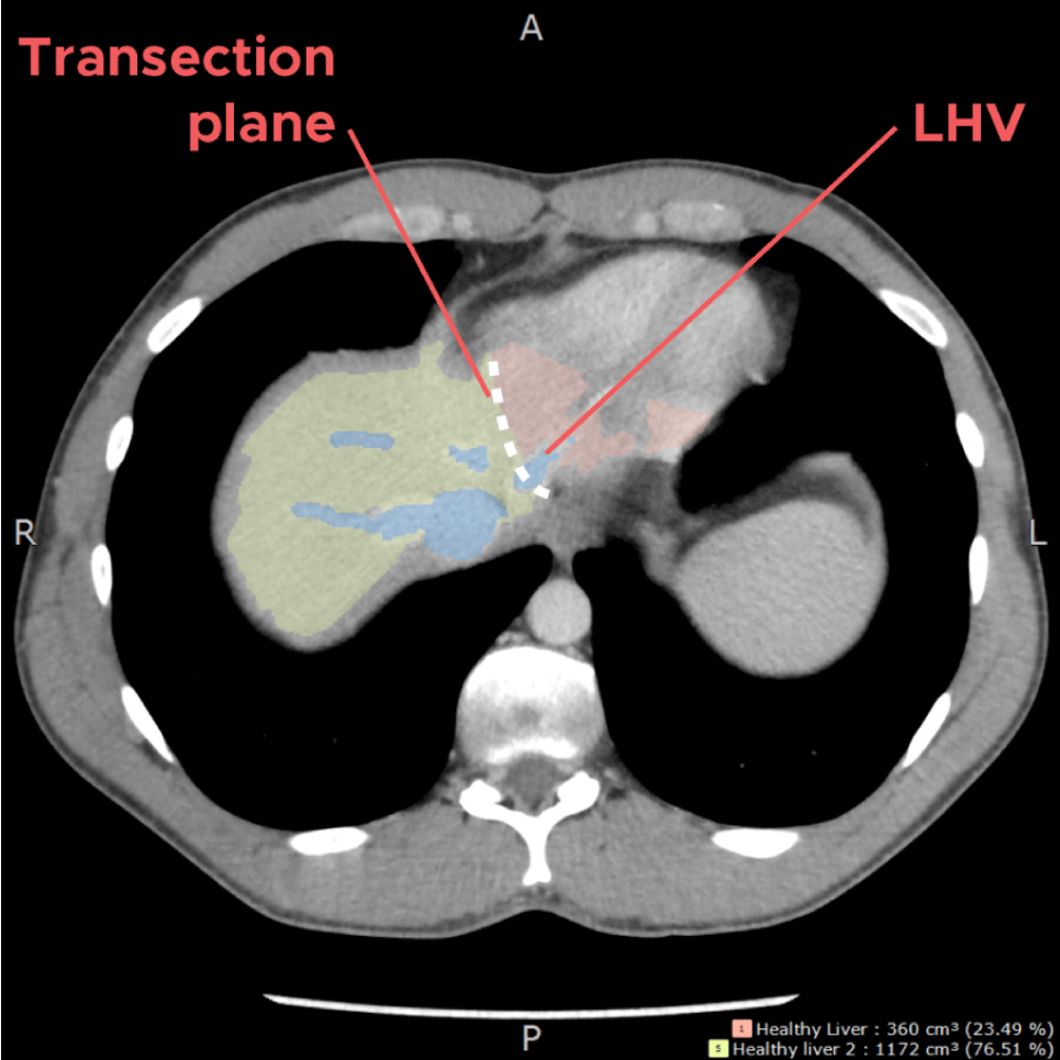
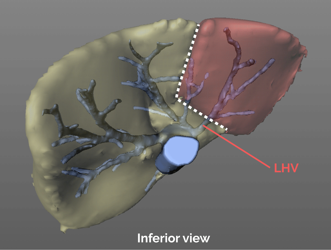
At the top of the liver, the transection plane would come across the left hepatic vein, to allow for adequate drainage for the graft. The MHV is preserved in the donor.
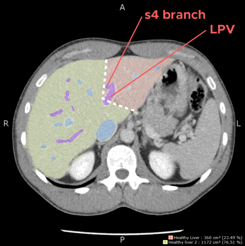
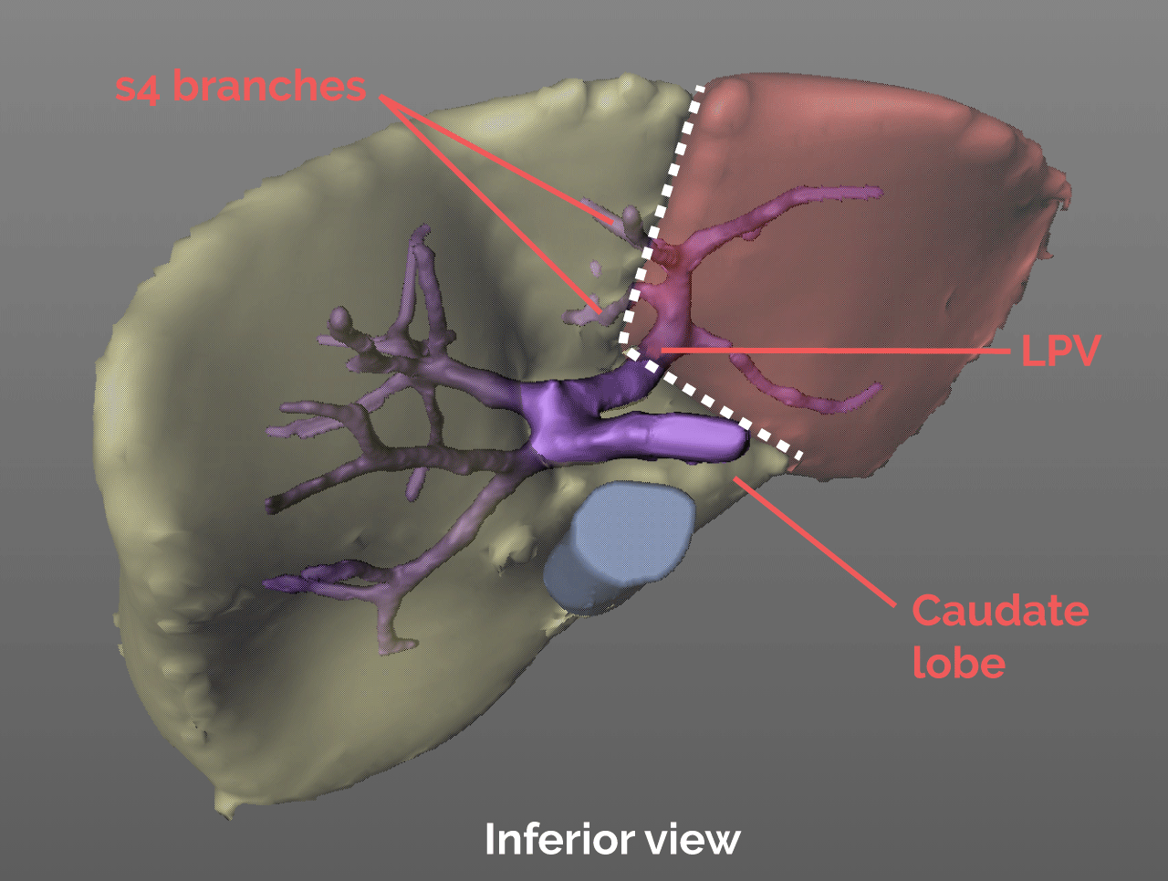
As parenchyma transection proceeds through Segment 4, and 1cm to the right of the falciform ligament, portal pedicles from the left portal vein going to the right should be anticipated and will be sacrificed.
In the porta hepatis, the left hepatic artery and left portal vein are identified. Small caudate branches are divided. This section of the transection plane is drawn with a more horizontal orientation to ensure the LPV is divided in a manner that preserves the MPV and RPV inflow in the donor, as well as the caudate lobe.
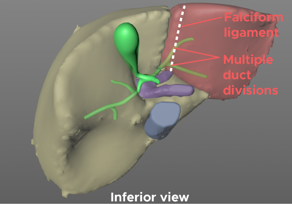
The rationale for positioning the transection plane 1cm from the falciform, is largely a consideration of the bile ducts, and avoiding any thermal injury to pedicles draining the left lateral graft. Additionally, setting the plane along the falciform would potentially result in dividing the segment 2 and 3 bile ducts proximal to their confluence in forming the main left hepatic duct, and therefore resulting in a graft with multiple bile ducts.
Thus, setting the transection plane approximately 1cm away to the right of the falciform increases the likelihood of an optimal biliary transection, and a graft with a single, well vascularized, bile duct.
Volumetric analysis
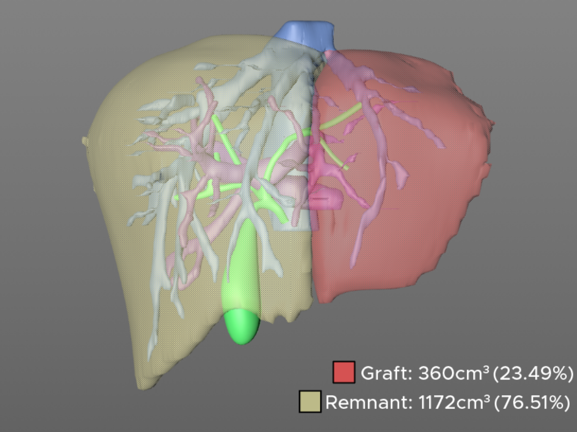
Once the plane is drawn, the corresponding liver volumes can be calculated for both the graft and remnant liver. The graft volume can then be used to calculate the graft weight/ - recipient weight (GWRW) ratio and to determine suitability of the graft for the recipient. Generally it is preferred for this ratio to be greater than 1, and the remnant liver to exceed 30% in the donor.
Both of these conditions are usually not a challenge to meet in left lateral segment donation from an adult to a child. An additional dimension to consider for the pediatric recipient, however, is the anterior-posterior and lateral dimensions of the graft which can be measured using the axial cuts of the CT scan and put in context upon sizing of the recipient.
Special thanks to Dr. Madhukar Patel, one of our current MOT/HPB fellows for his help putting together this blog post. We look forward to covering more in the field of 3D visualization and surgical planning, so stay tuned and please subscribe to our newsletter if you'd like monthly updates from our atlas.
-The TVASurg team