
The annual Association of Medical Illustrators meeting has just wrapped up, and this year TVASurg production team members gave TWO presentations! What follows is a summary of the "tech talk" Senior Biomedical Communicator Paul Kelly gave on using the software 3DFlow Zephyr for making photogrammetry-based 3D models for surgical subjects.
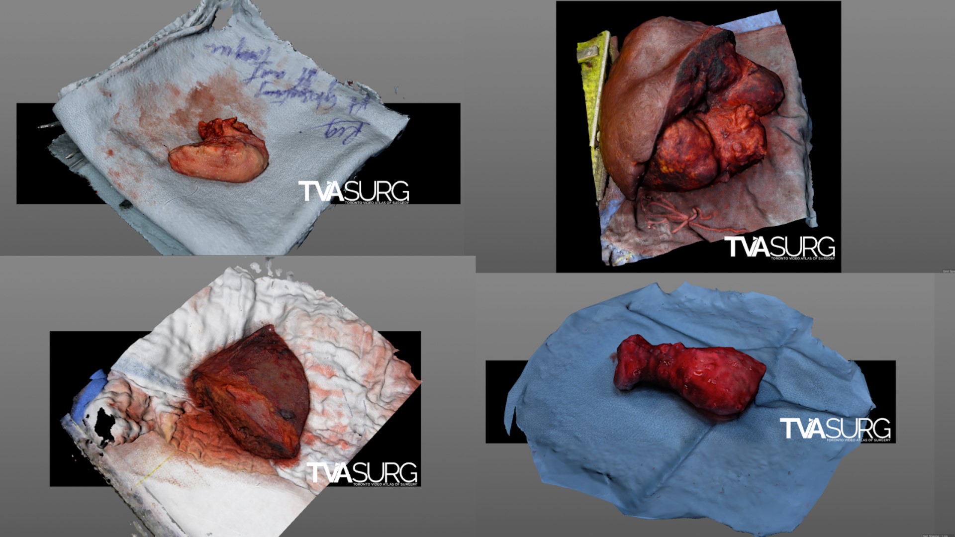
Capturing a photography-based 3D snapshot of an intraoperative surgical field has tremendous educational potential. The logistical limitations of a live operation and sterile field produce unique challenges–a single camera cannot compensate for the inherent movement of living human anatomy, and existing multi-camera rigs are too large and expensive to be practical in the OR. We are currently developing and testing novel approaches to address these challenges. Fortunately, filming various surgical procedures that involve resections provides ideal subjects for testing and developing this workflow, and production of these assets (available for viewing on SketchFab) will be explained in this talk.
OVERVIEW
3DFlow Zephyr is a photogrammetry software for PCs. The “Lite” version of the software (perpetual license) is decently priced at 150 euros, the full version is a bit more expensive, but most of its premium features are for drone photogrammetry, so you may not need those. Some of the full version features that may be worth considering though are:
- Export point clouds
- Export 3D PDFs
- Generating “orthophotos”
- Control points for more precision
3DFlow Zephyr is an “automated” photogrammetry tool, meaning most of the settings in the software have already been fine-tuned and any errors you encounter in reconstructions will likely be due to mistakes made in the photography process (e.g. “noisy” surfaces are often the result of poor images). So in each step of the process you can get away with using the default settings, but 3DFZ also gives you the option to go in and precisely tweak settings if you want to. Of course, you’ll have to know what settings you’re tweaking and why.
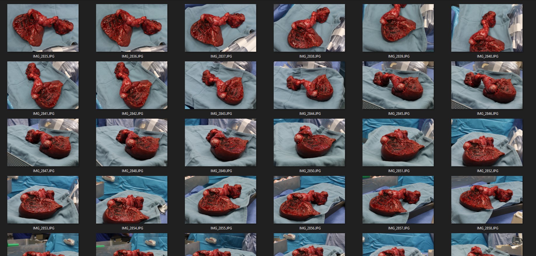
TAKING PHOTOS
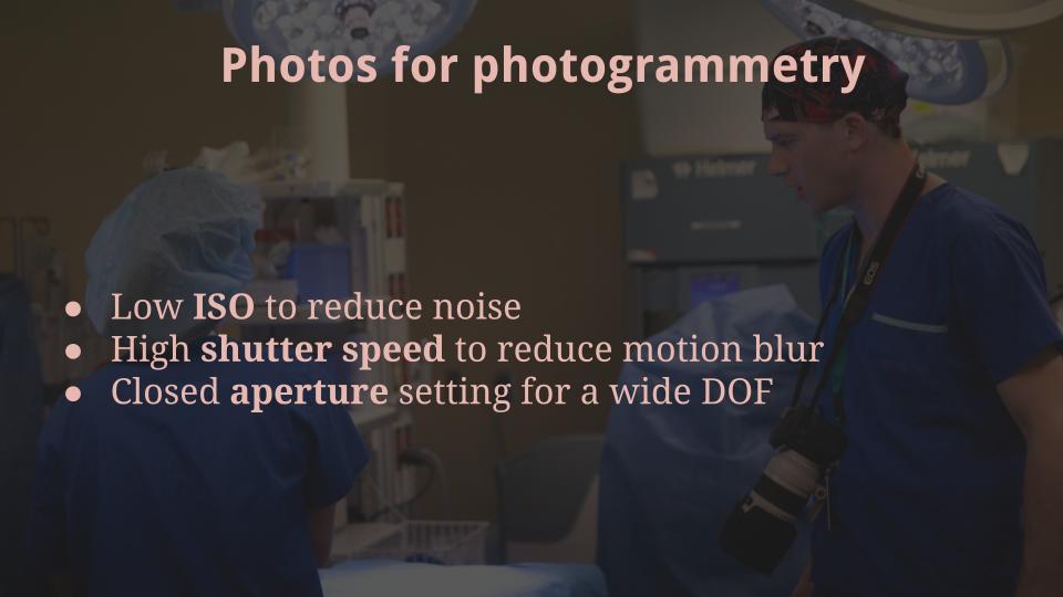
You want to take photos of a subject brightly lit, with a strong diffuse light source. Always try for
- a low ISO,
- high shutter speed,
- and wide DOF / closed aperture
You also want to stick with a fixed focal length, so don’t zoom in and out on your lens. You can move forward if you want to get more of the subject in frame, but don’t twist the lens to do so. Some people even tape down their lens once they have a zoom distance they like. Try to get photos from every possible angle, moving around the subject in a steady, consistent manner. Keeping the previous tip in mind, you can get in close and take image sets of “chunks” of a subject as well. This can help increase detail in certain areas and help with “overhangs”, but these photos should be part of a larger photoset that includes the subject as a whole.
FOLDER STRUCTURE
Here is a recommended folder setup:
- Photoset #1
- Images
- JPG
- CC
- DNG
- RAW - Process
- Screenshots - Recons
- OBJ files
- Texture maps - Scenes
- 3DFZ files
- C4D files
- ZBrush projects
- Images
- Photoset #2...
Basically I’d recommend organizing your project based on a batch of consistent photos. Photogrammetry requires that the subject remain unaltered in every photo, so, if something changes in your scene, consider it a new batch with a new folder structure.
WORKFLOW OVERVIEW
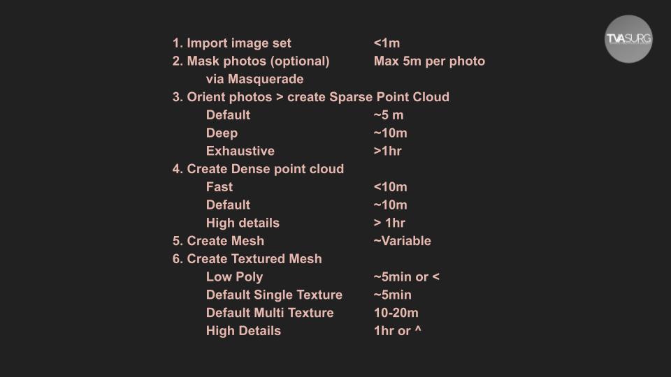
All projects in 3DFZ follow the same general process: you begin by importing photos, masking the photos if necessary, generating a sparse point cloud, refining to a dense point cloud, generating a polygon mesh, and finally applying the colour information to the mesh as an exportable texture map.
It’s important to acknowledge the difference between point clouds and meshes, because they are two different types of data. Point clouds have the RGB information applied to the vertices, whereas our ultimate goal is to have the RGB information applied from the source photos to the polygons of a 3D mesh object, a 3D mesh being a lattice of connected points. Here are the basic steps within 3DFZ and some time estimates for each:
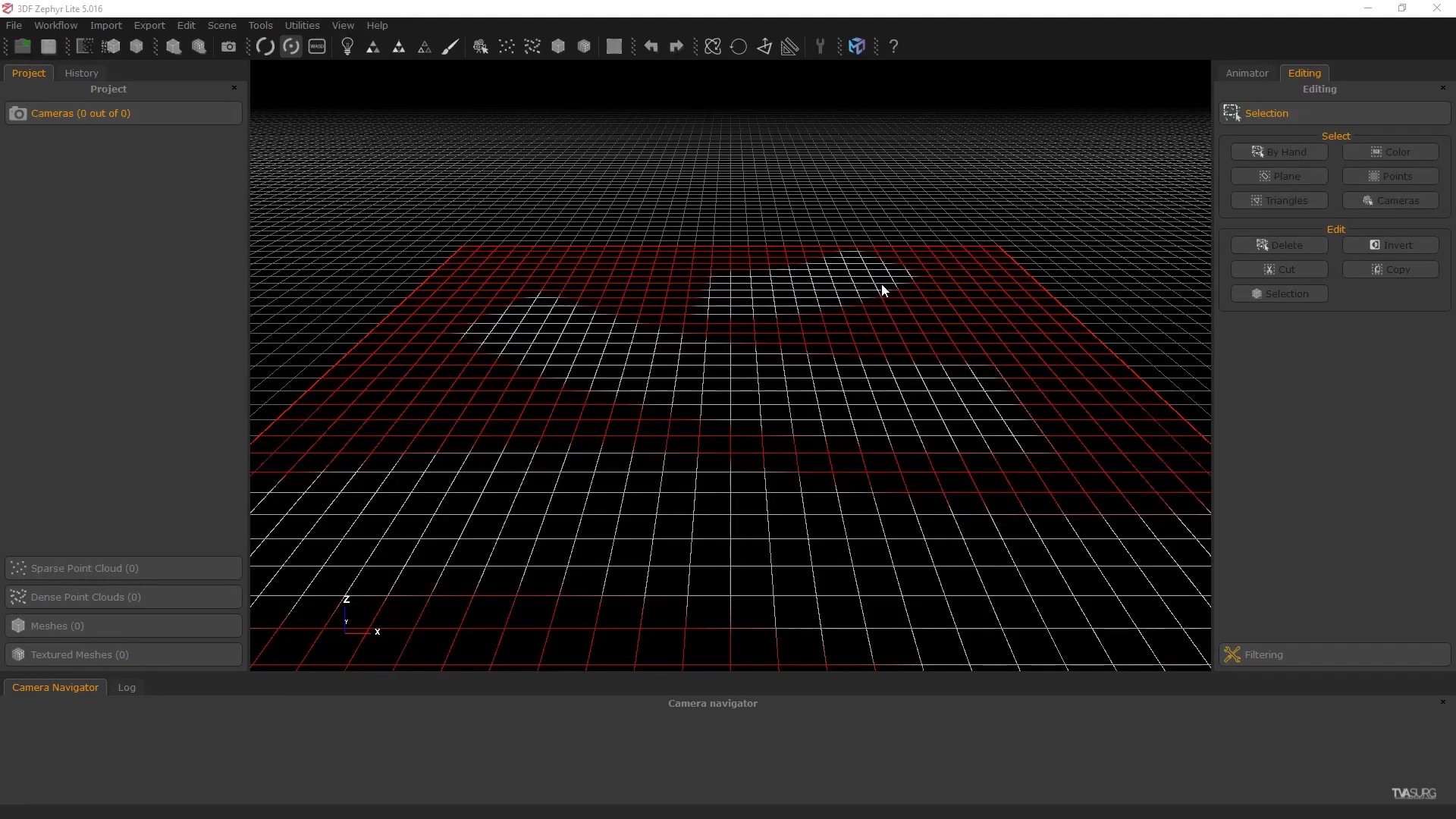
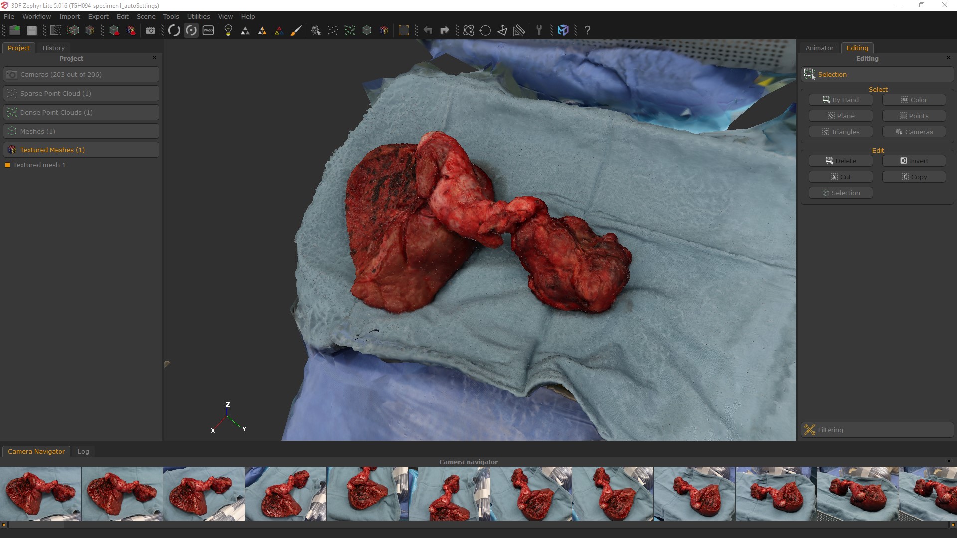
USER INTERFACE
Most of the tools you’ll be using are easily found along the top of the UI:
- Workflow shortcuts
- Screenshot button
- Orbit from click
- Orbit from scene centre
- Lit/unlit mesh
- Point cloud colours on/off
- Texture map on/off
These come into play later when you are working directly with your reconstructed mesh.
The UI appearance can be tweaked by going to Tools > Options > Rendering. Most importantly, you may want to change the viewport BG colour here. White, black, dark or light grey may work
better for different individuals.
The grid plane is also something you may wish to toggle on or off. You can find this in Tools > Options > Rendering > Grid > Show Grid
IMPORT PHOTOS + GENERATE SPARSE CLOUD
Open 3DFZ and go to Workflow > New Project (Ctrl+N). You’ll be prompted to import photos so navigate to your photoset. Select the ones you want and you’ll see some metadata about the pictures.
Run a Sparse Cloud reconstruction. This will open up a window that tells you how many photos were successfully reconstructed. For those that were not included, we can go back and try again with masks or higher settings to see if we can bring them in. Typically we’ll start with “Close Range” + “Fast” and if it doesn’t use all the photos, try again with “Close Range” + “Deep”
If images aren’t included in recon, you can also try to add them back in manually by right-clicking on the image under Project >Cameras (greyed out image with (N/O)) and go to “Orient Selected”. When prompted, click through the recon options and pick an image that is close to the unused one then hit “Run orientation”.
Masquerade is the masking process for 3DFZ. After you’ve imported your photos you’ll have the option to mask them. Once the dialogue window is open, use the foreground/background paint tools to get an initial coverage established. You can then go in and tweak the masks, but for projects with a large number of images, this can get tedious, so dragging the rectangle marquee over the main subject and masking it should be adequate. Even with this quick-and-dirty approach, it can still take a lot of time, so only do this on photos that are being discarded from the sparse cloud generation, then try them again.
One thing to note about Masquerade, is that it will automatically open every photo in the folder you’ve selected, so this is one reason why rather than keep all photos from a shoot in one folder, separate them into batches based on what you intend to reconstruct.
If you have to do a lot of masking, a helpful feature is to use the “Copy the current mask to the next image” button at the bottom left of the Masquerade pop-up.
ADVANCED SETTINGS
Surgical photogrammetry is unlike other use cases in that it is basically impossible to return to your subject later to take photos again, and typically we have very little control over the lighting situation in the OR. Sometimes there are additional lights we can access, but those are usually harsh and produce hard shadows, not the soft diffuse light sources we would want for ideal photogrammetry capture. As a result, we usually get suboptimal photos to use, so knowing how to adjust the software settings to get the best results possible is important.
3DFlow Zephyr shares the same math formulas used in all photogrammetry software. While each goes about these in different ways, generally they are all going to perform a “Structure from motion” or SFM process, a “Multiview stereo” process, a surface reconstruction or mesh generation process, and finally a texture extraction process.
After following the previously mentioned steps to optimize the sparse cloud, there are some additional settings we can tweak when we start the reconstruction. They are:
- Keypoint Density affects the “Keypoint extraction” portion of the SFM process, and increasing this setting will increase the maximum number of keypoints the software extracts from each image. Increasing this setting doesn’t always produce better results though because you can end up asking the software to perform redundant tasks here.
- Matching Type can speed up the matching phase by using clusters of points.
- Matching Stage Depth affects the “Pairwise image Matching” portion of the SFM process
- Reconstruction Engine will affect the “Mesh Generation” phase.
- Bounding box affects the “Mesh Generation” phase by pre-emptively discarding distant
points. - Photo Ordering affects the “Neighbor image search” phase, which is an earlier part of
the process. If you’re taking photos while walking around with a DSLR, this will almost
always be “Unordered”, you would only really use the other settings if you had a camera
rig setup or if using a drone.
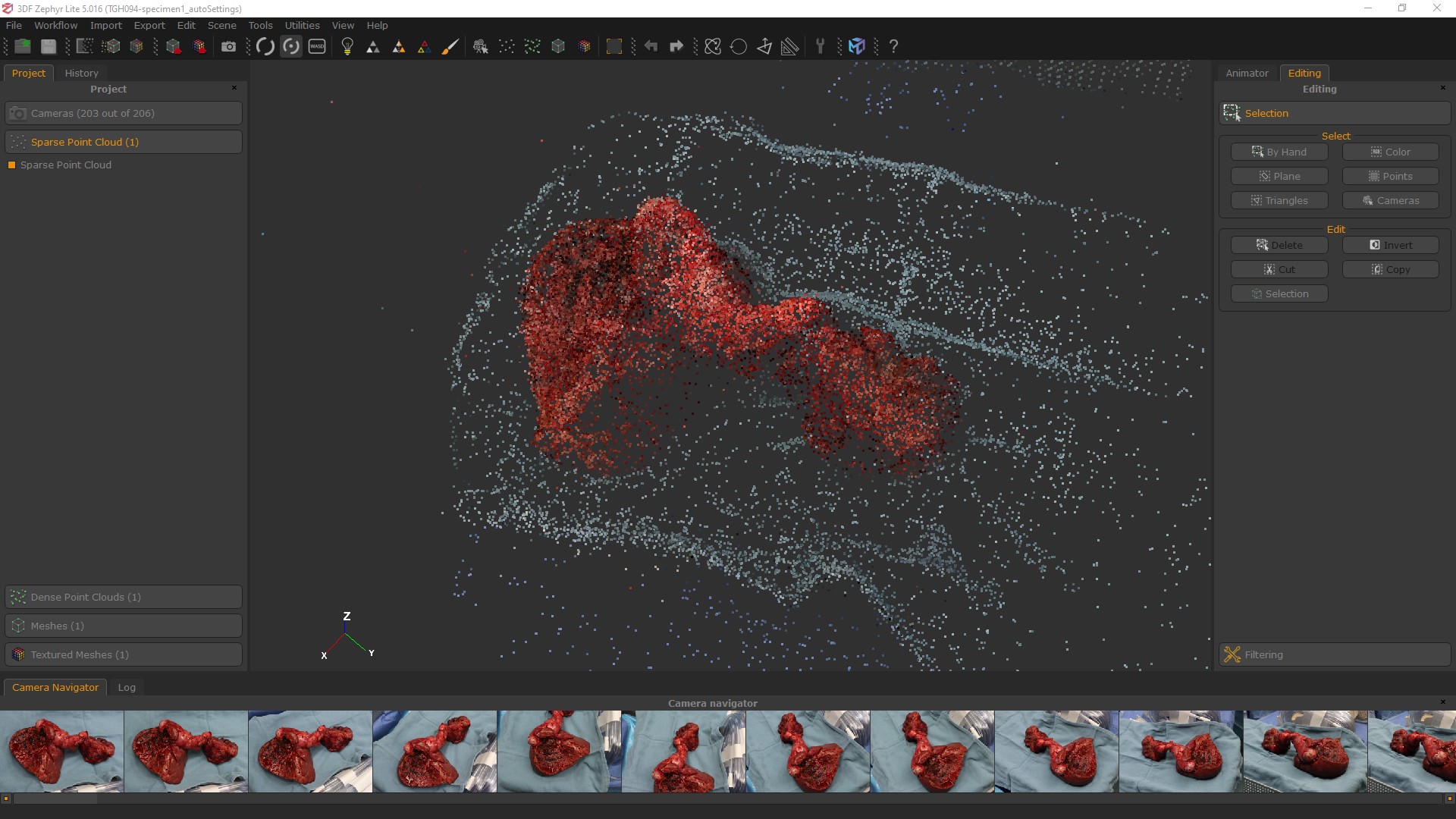
SPARSE CLOUD EDITING
Once you’re satisfied with the amount of photos included. Orbit around your sparse point cloud.
- Click and drag with the LMB in the workspace to rotate
- Click and drag with the MMB to pan
- Use the scroll wheel on your mouse to zoom
If you don’t have a 3-button mouse, you can also use - Ctrl+LMB to pan
- and Shift+LMB to zoom
When you have your point cloud or mesh loaded in the viewport, you’ll also see little pyramid icons for the camera positions. You can adjust the size of these in: Tools > Options > Rendering > Cameras > Scale To turn them off just pull the slider all the way to the left.
Inspect your sparse point cloud and look for any stray points that are far away from the rough point cloud. These are probably errors and may cause problems for the later stages, so I suggest deleting these now at this stage before proceeding. On the right hand column of your UI you’ll see the “Editing” tab. Under “Select” click on “By Hand” and a pop up “Selection” window will open. Use whichever tools work best for your situation to select points.
Note the “Mode” section below the “Tool” section. When you’re selecting points, your LMB navigation control is frozen, so unlock it by clicking “Pause” (the MMB controls still work though).
If you select points by mistake or want to refine your selection, you can switch between “Add” or “Remove” under “Mode”. With the “Selection” window open, you can still hit the buttons under the “Edit” portion of the “Editing” tab, so click on “Delete” to remove the stray points. You can also invert your selection here.
Leveling your points clouds and reconstruction with the ground plane can make viewing and editing them much easier. 3DFZ has built-in tools to do this automatically.
- Define the “up” vector using a triangle. Pick 3 points in a counter-clockwise manner.
- You can also use the Transform tool to adjust. When done, click “apply” in the transform window to apply the transformation.
Measuring your reconstruction can also be very useful for maintaining a real-world scale in your scenes, especially for exporting the model to be used in other software. The full version of the software has tools to interpret real-world measurements derived from the metadata in the photos, but for the Lite version, you can do this using default tools and a little math IF you remember to take measurements while photographing. For surgery, this is made easy if a sterile ruler strip can be placed in at least one of the photos next to the subject.
- Use the Measure tool to take arbitrary measurements in the scene
- Divide the known size of the object by the arbitrary value.
- Scale the scene up by the resulting value with the Transform tool
Measure in your scene the largest possible consistent measurement. Avoid small objects as reference measures whenever possible because inherent errors in the process will get amplified.
Cropping the mesh can be done using the Bounding Box tool. If you’ve leveled your point cloud, the initial orientation of the bounding box will be out-of-sync because it starts out in the
same orientation your point cloud did. To re-orient, click on “Reset” on the far right of the “Bounding Box Edit” window. Click and drag on a plane of the box to adjust it.
When working with a few photos, after the sparse point cloud is generated, adjust the bounding box to expand past its default, it will probably be cutting off points.
You can toggle the bounding box visibility with the checkbox at the bottom of the pop-up.
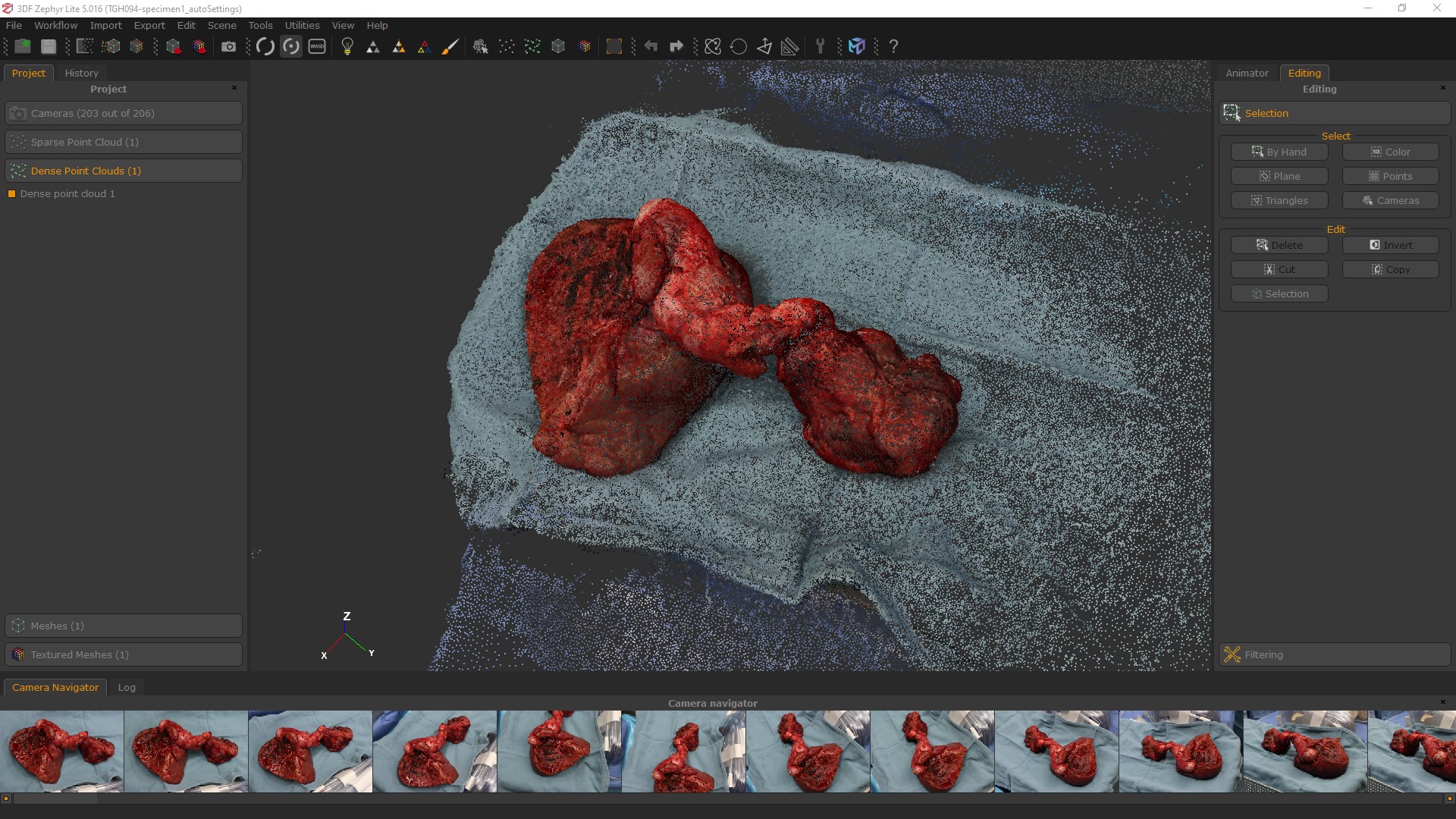
DENSE CLOUD
With the sparse cloud leveled, cropped and bounding box still active, now we’ll make a dense point cloud.
Go to Workflow > Advanced > Dense Point Cloud Generation or the button for “3D Model Generation”. If you click the button in the toolbar, this will run through the Dense Point Cloud and Mesh Generation steps together, if you don’t anticipate needing to tweak the dense point cloud. If you want to check on each stage of the process though, go through the Workflow menu. You may want to do this to check on how the dense point cloud looks, sometimes there are details that you can’t see from the sparse cloud.
Once complete, click on the “Finish” button along the bottom and you can see your results.
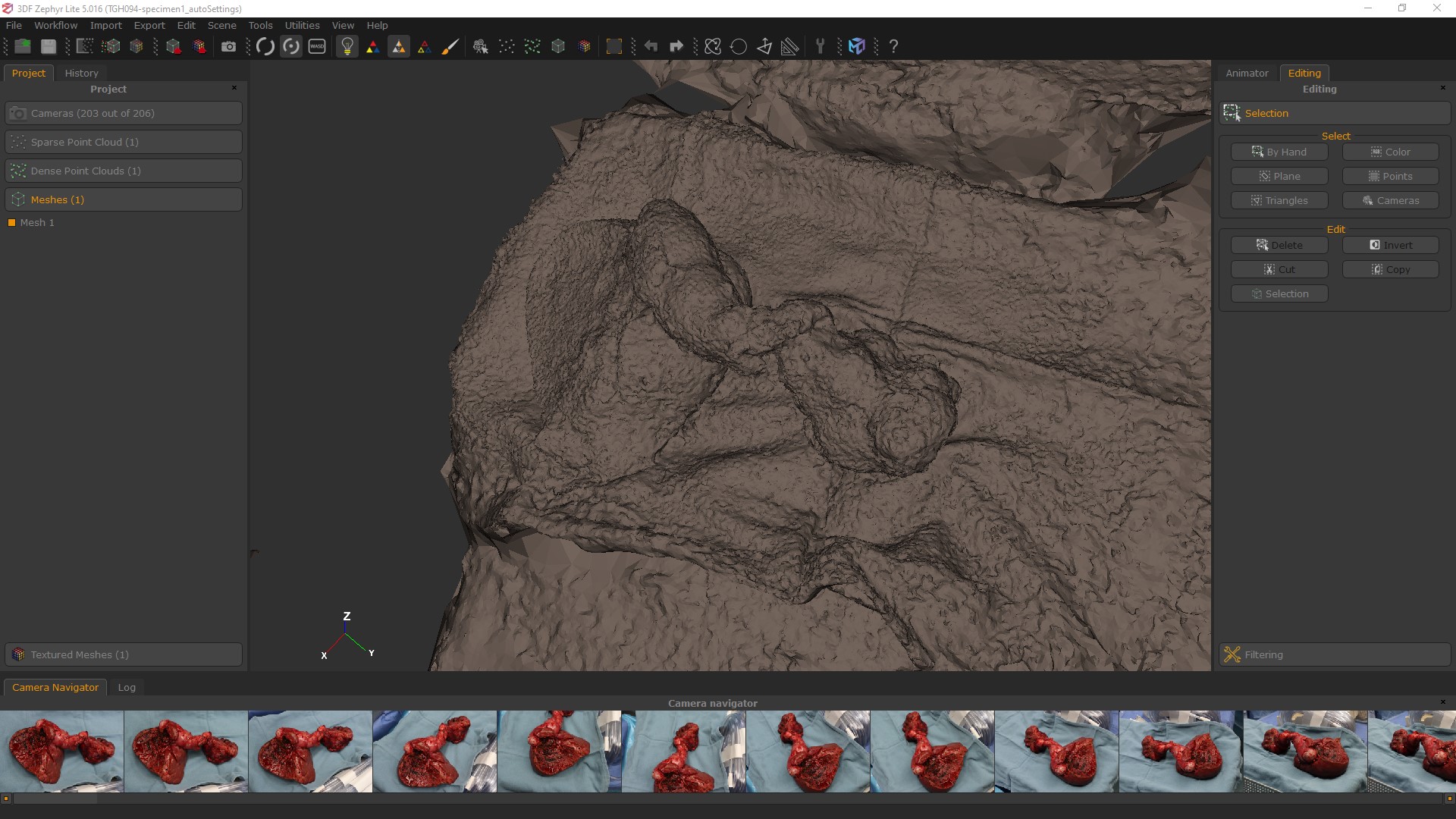
MESH EXTRACTION
When you have a dense point cloud to work from, you can convert it into a polygon mesh by going to Workflow > Advanced > Mesh Generation or clicking on the “3D Mesh Generation” button at the top of the UI. There is a lightbulb icon in the toolbar along the top of the UI, and next to it there are three pyramid-shaped icons. These toggle the visibility modes for the model. You can turn off/on the scene’s default lighting with the lightbulb, toggle the mesh coloring, and enable wireframe view. These modes will help you inspect the model.
If you export this now, you’ll only have a base mesh, the color information is only in the 3DFZ scene. To export the color information in a texture map you’ll have to generate and export a textured mesh.
TEXTURED MESH
As you create different versions of point clouds and meshes, be aware of which one is active in the “Project” tab.
To create a texture map, go to Workflow > Textured Mesh Generation or to the Textured Mesh Generation button in the toolbar. Choose a preset and click “Run”.
Advanced Settings
You can set the Max texture size, image resolution, Max vertices, and Max number of textures here.
Once the textured mesh is generated, you have some additional tools in the software you can use to refine the mesh. Go to Tools > Mesh Filters >... and select the Decimation filter to reduce the poly count, which you can guide towards a target number. The Retopology filter will try to spread the polygons out evenly. These can help give you a better mesh for uploading directly to an online site like SketchFab, or, a better base to start off with if you want to further refine it in ZBrush.
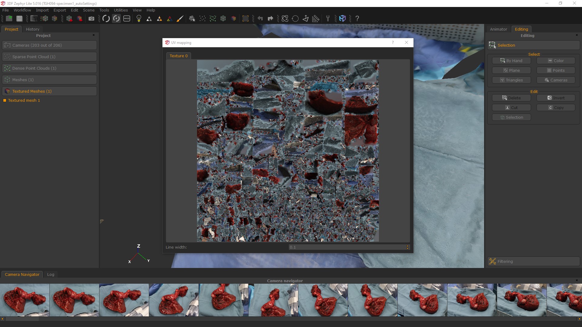
If you Rt-Click on the Textured Mesh in the “Project” panel, you can inspect the UVs. The UV map representation in 3DFZephyr will show you that the meshes in this program are always with Tris, no quads. So if you import a quad mesh it will automatically triangulate it.
EXPORT
Once you’re ready to export, click on “Export Textured Mesh” from the toolbar. In the pop-up window you can select your file format, usually OBJ is fine but FBX is also popular. There’s also an option to upload directly to SketchFab which is pretty cool. Definitely export with Normals.
You can select whether you want to export as a single texture, though depending on previous settings you used it may only generate a single texture map regardless. For file format, JPG or PNG are fine for most purposes. EXR and TIFF32 only really come into play if you are doing some advanced editing, so for most use cases you can ignore these. Unless you know what you are doing with it, don’t export to TIFF32 to try and get higher res, you’ll just end up with a huge file that isn’t that much better than a JPG.
In case you’re wondering what “Export to UDIM” does, this is for multiple texture maps and it gives each a serial number so other software that knows how to read UDIMs can read them. You can include a lot of maps for a single model with UDIMs, thus maximizing the image resolution of each map.

RE-IMPORT
If we refine our mesh in another software like ZBrush, we can re-import a cleaned up, retopologized, optimized UV-mapped model into 3DFZ, and re-apply the texture information. Go to Import > Import Mesh with UV Map at the top of the UI. Now you will encounter error messages when you try to import a mesh here if there are problems with it. Specifically, if you have geometry that’s doing erratic things like overlapping on itself, or N-gons, or little glitches in the surface like “butterflies”. So you’ve got to make sure it’s a clean mesh and you haven’t changed it’s position, scale or rotation.
You’ll get a message letting you know if the model can be loaded or not. In the import settings, you can select which textured mesh to transfer the texture data from. Under “Texture Settings” select “None - Recompute visibility”, set your Max texture size and click “Import” at the bottom.
The process is pretty much auto-magic. If the model imports OK, 3DFZ will re-apply the color information from the photos to the new mesh with optimized UVs. Using the previously mentioned UV and mesh inspection tools, you can verify that this is so. Re-export and check out your new, high-res, optimized texture map!
So that's an overview of making photogrammetry-based 3D models of surgical subjects using the software 3DFlow Zephyr. If you'd like to learn more about using this software, we'd recommend checking out tutorials from 3DFlow Zephyr, as well as Eugene Liscio from ai2-3D Forensics, who teaches an in-depth course on using 3DFlow Zephyr for models to be used in forensics work:
Thank you so much for putting all this information together, it is very comprehensive and useful. I have used Agisoft/Metashape and a few phone photogrammetry applications previously in the anatomy dissection lab and have still learned quite a bit from your report.
Happy to hear it was helpful, thanks so much for letting us know Eva!