
Last month we reviewed some basics on how to reconstruct 3D computer models based on patient scan data, using an open source 3D reconstruction software, 3D Slicer. A more in-depth post on modeling can also be found here.
Apart from utilizing them in our educational videos, these 3D models generated from reconstruction softwares also serve as a surgical pre-planning tool, particularly for living donor liver transplant cases. They are not only used to help calculate volumes of liver parenchyma in both the graft and remnant liver, but also to aid in visualizing anatomical structures along the anticipated transection plane.
Here we will provide a case example of how 3D models generated from 3D reconstruction software are used in surgical pre-planning for right lobe donor hepatectomy.
The 3D reconstruction software used by our transplant team is Intrasense Myrian, which we will be featuring in the workflow below. Similar open-source plug-ins are available for 3D Slicer as well.
Simulating the cut
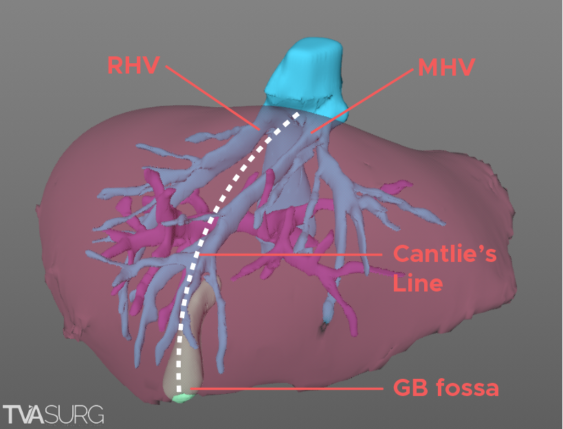
For a right lobe hepatectomy, we often start by tracing out a plane following Cantlie's line, an imaginary division which represents the principle plane between the right and left liver.
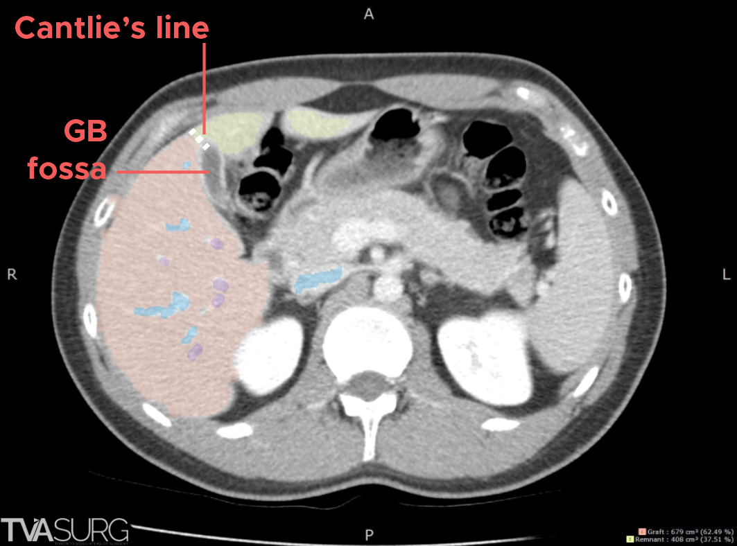
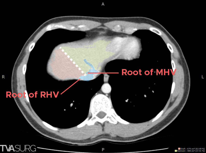
This line starts inferiorly from the gallbladder fossa, and is extended superiorly towards the right/middle hepatic vein groove. Shown above are selected CT slices that demonstrate these anatomical landmarks.
The line closely follows the course of the middle hepatic vein.
Vascular structures along the plane
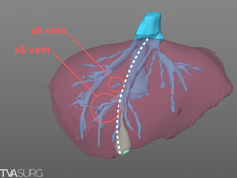
With the transection plane guided by the MHV, certain venous branches are anticipated to be divided within the liver, for example, the segment 5 and segment 8 tributaries.
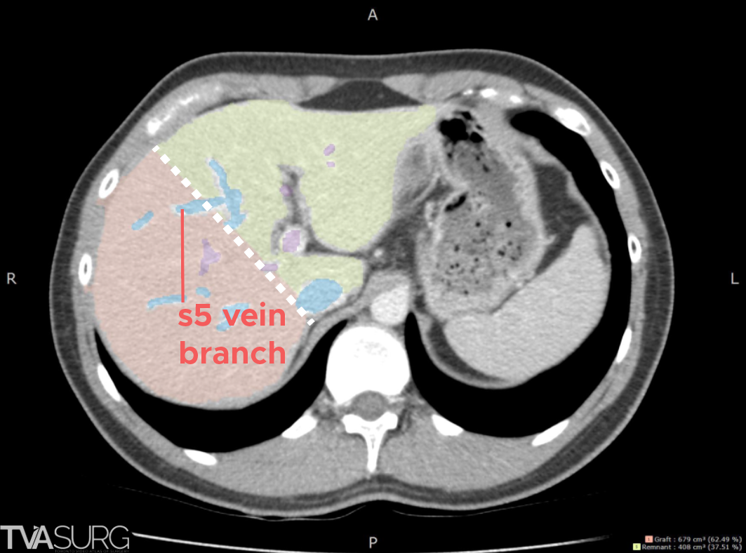
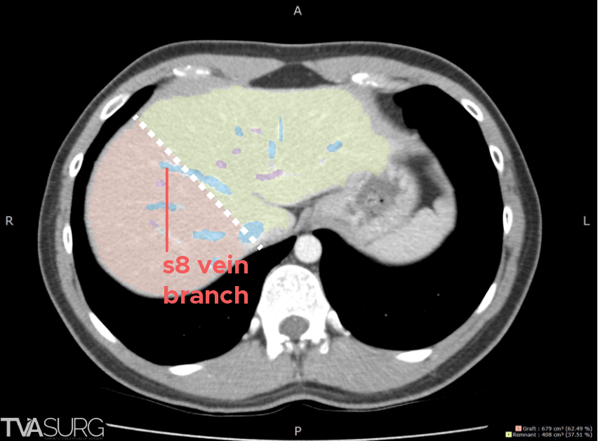
We can anticipate these branches based on Cantlie’s line drawn on the axial images of the CTl.
Considerations at the porta hepatis
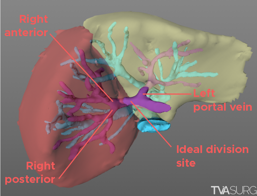
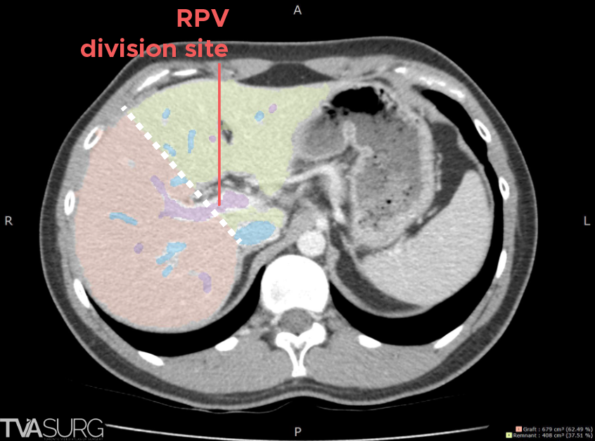
At the porta hepatis, the plane will encounter the portal vein. Donor anatomy permitting, the ideal outcome for a right lobe graft is for a single portal vein.
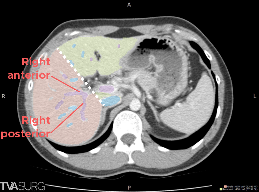
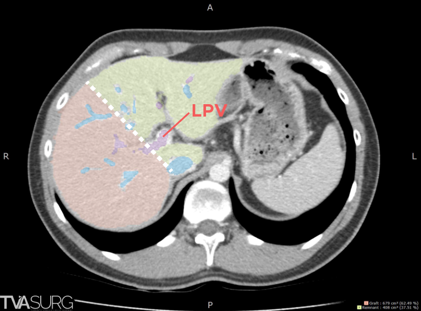
The transection plane may need to be slightly adjusted to allow for this as overshooting to the right side may result in dividing the right anterior/posterior portal vein branches, while overshooting to the left side may impinge upon the left portal vein - both suboptimal outcomes for the graft and remnant.
The hepatic arteries and ducts are typically assessed through different imaging series; for sake of simplicity, we will focus on those topics in a future blog post.
Volumetric analysis
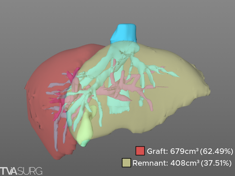
Once the plane is drawn, the corresponding liver volumes can be calculated for both the graft and remnant liver. The graft volume can then be used to calculate the graft weight - recipient weight (GWRW) ratio, to determine suitability of the graft for recipient.
The remnant liver volume is generally used as a safety benchmark - having it over 30% of total liver volume is preferred to ensure donor safety and recovery, however, in highly selected live donors, a future liver remnant (FLR) of less than or equal to 30% is permissible. In cases where the FLR or GWRW is borderline, the transection plane can be re-drawn, making a note to reflect this adjustment when performing parenchymal division intraoperatively.
Special thanks to Dr. Madhukar Patel, one of our current MOT/HPB fellows for his help putting together this blog post. We look forward to covering more in the field of 3D visualization and surgical planning, so stay tuned and please subscribe to our newsletter if you'd like monthly updates from our atlas.
-The TVASurg team
Excellent work. One more add on can be using 3D MRCP /MRI can show acurate biliary anatomy and the bile duct division plane predicting the number of ducts. Which can be a great help in robotic donor hepatectomies.